

7404 Integrated Circuit (IC): Datasheet, Pinout, Pin Diagram, Truth Table
Update Time: Nov 24, 2023 Readership: 10680
Contents
The 7404 IC, also known as the hex inverter, is comprised of six independent inverters, each capable of transforming logic high signals to logic low and vice versa. Its versatility makes it an indispensable building block for numerous applications, ranging from basic logic gates to more complex digital circuits. As an integral part of the 7400 series, this IC plays a crucial role in the construction and implementation of various digital circuits. We delve into the specifics of the 7404 IC, providing essential information including its pinout, pin diagram, and truth table.
7404 Integrated Circuit Description
The 7404 full name is 7404 Hex Inverter, which indicates that it is a member of the 7400 series and specifically functions as a hex inverter.
The 7404 hex inverter, a vital component within the 7400 series of TTL integrated circuits, stands out in digital electronics for its fundamental capability to invert input signals. Beyond its basic operation, the hex inverter's features enhance its applicability across various electronic devices.
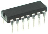
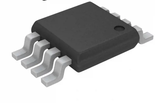
With six independent inverters, each with a single input and output, the 7404 is meticulously engineered to operate within a 5-volt supply voltage range, accommodating a maximum current of 40 milliamps. Its versatility is emphasized by the availability of different packages, including the widely used DIP and the compact SOIC packages.
The 7404 hex inverter's adaptability makes it suitable for a diverse array of applications, from basic logic circuits to pulse generators and power inverters. Its reliability and low power consumption make it ideal for battery-powered devices. Noteworthy for its simplicity and user-friendly design, the hex inverter adheres to a standard pinout and operates seamlessly with a single 5V supply, facilitating integration into various circuits for applications ranging from breadboard prototypes to DIY electronics projects.
7404 Integrated Circuit Absolute Maximum Ratings
|
Supply Voltage |
7V |
|
Input Voltage |
5.5V |
|
Operating Free Air Temperature |
0°C to +70°C |
|
Storage Temperature Range |
-65°C to +150°C |
7404 Integrated Circuit Features
-
Six Hex Inverters
The 7404 IC integrates six independent hex inverters into a single package, providing multiple inverters in one unit.
-
Outputs Directly Interface to CMOS, NMOS, and TTL
The outputs of the 7404 are designed to directly interface with various logic families, including CMOS, NMOS, and TTL, offering versatility in circuit integration.
-
Large Operating Voltage Range
The IC operates over a large voltage range, accommodating diverse voltage levels within the specified limits.
-
Wide Operating Conditions
Designed to function effectively across a wide range of operating conditions, providing reliability and stability in diverse environments.
-
Not Recommended for New Designs
The 7404 is labeled as "Not Recommended for New Designs," indicating that it is considered outdated or may have newer alternatives available in the market.
-
Use 74LS04
The recommendation to use the 74LS04 suggests that, for new designs, it is advisable to opt for the 74LS04 variant rather than the standard 7404. This may be due to improvements in the LS (Low-power Schottky) series, which offers advantages in terms of power consumption and performance.
7404 Hex Inverter IC Specifications
|
Specification |
Value |
|
Maximum Current Output |
8mA |
|
Supply Voltage Range |
4.75V to 5.25V |
|
Operating Temperature Range |
0°C to 70°C |
|
Maximum Supply Voltage |
7V |
|
Maximum Rise Time |
15ns |
|
Maximum Fall Time |
15ns |
|
Output Type |
TTL |
|
Lead-Free |
Yes |
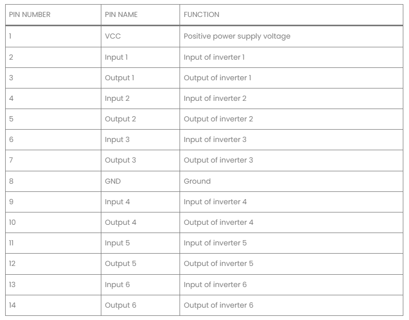
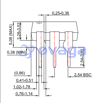
7404 Datasheet
7404 Pinout
The 7404 IC, or the 7404 Hex Inverter, features a straightforward pinout configuration. It consists of six independent inverters, each represented by a specific pin.

Pin Description:
1A (Input): Input for the first inverter.
1Y (Output): Output for the first inverter.
2A (Input): Input for the second inverter.
2Y (Output): Output for the second inverter.
3A (Input): Input for the third inverter.
3Y (Output): Output for the third inverter.
4A (Input): Input for the fourth inverter.
4Y (Output): Output for the fourth inverter.
5A (Input): Input for the fifth inverter.
5Y (Output): Output for the fifth inverter.
6A (Input): Input for the sixth inverter.
6Y (Output): Output for the sixth inverter.
GND (Ground): Ground reference for the IC.
VCC (Supply Voltage): Positive supply voltage (usually +5V).
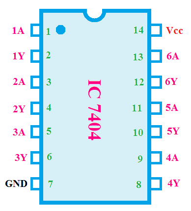
IC 7404 Pin Diagram
7404 IC Truth Table
The truth table for the 7404 Hex Inverter outlines the relationship between the input and output states for each of its six inverters. In general, an inverter (NOT gate) produces an output that is the logical complement of its input.
|
Input (A) |
Output (Y) |
|
0 |
1 |
|
1 |
0 |
This truth table applies to each of the six inverters within the 7404 IC. When the input (A) is 0, the output (Y) is 1, and vice versa.
Function of 7404 IC
The 7404 IC functions as a NOT gate, and its primary purpose is to invert the input signals.
-
NOT Gate Operation
The 7404 IC contains six individual NOT gates, also known as inverters.
Each inverter performs a logical inversion on its input signal.
-
Logical Inversion
The output of each inverter is the logical complement (opposite) of its input state.
When the input is high (1), the output is low (0), and when the input is low (0), the output is high (1).
-
Universal Logic Function
The NOT gate is a fundamental building block in digital logic circuits.
It can be used to construct more complex logical operations and is a key component in the design of various electronic systems.
-
Six Independent Inverters
The 7404 IC conveniently integrates six independent inverters into a single package.
Each inverter within the IC operates autonomously, allowing for multiple inversion functions in one unit.
7404 IC serves as a versatile NOT gate, providing logical inversion for six independent signals. Its simplicity and ubiquity make it a fundamental component in digital electronics and a crucial building block for constructing various logical functions and circuits.
Applications of the 7404 Hex Inverter
-
Logic Gates
The 7404 hex inverter is widely employed in the creation of logic gates, such as NAND and NOR gates. When multiple inverters are combined, they can form the building blocks for more complex logical operations.
-
Oscillators
In oscillator circuits, the 7404 hex inverter is utilized to generate periodic waveforms. Its ability to invert signals is harnessed to create oscillating outputs, crucial in clock generation and frequency synthesis.
-
Power Supplies
The 7404 is often integrated into power supply circuits to manage and control signals. Its role in logic inversion proves valuable in maintaining stable power supply conditions.
-
LED Drivers
The 7404 hex inverter is utilized in LED driver circuits where it helps control and drive LEDs. Its ability to invert signals is leveraged to manage the switching of LEDs efficiently.
-
Appliances Using Logical Inverters
Appliances with logical inverters, such as consumer electronics, may utilize the 7404 for various control and signal processing tasks.
-
Memory Units and Storage Applications
In memory units and storage applications, the 7404 can play a role in signal conditioning and control within the digital storage and retrieval processes.
-
PCs and Notebooks
The 7404 hex inverter may find application in PCs and notebooks for tasks involving logical signal processing, interfacing, or control functions.
-
Various Digital Electronics
Its broad compatibility and simplicity make the 7404 suitable for a myriad of digital electronic applications, providing logical inversion where needed.
-
Networking Gadgets and Systems
In networking devices and systems, the 7404 may be used for signal conditioning, logic processing, or interfacing within the broader digital communication framework.
-
Digital Systems
The 7404 hex inverter is a fundamental component in the design of digital systems, contributing to logical operations, signal conditioning, and control functions.
Advantages and Disadvantages of 7404 Hex Inverter
|
Advantages |
Disadvantages |
|
Low Power Consumption |
Limited Output Current |
|
High Noise Immunity |
Limited Voltage Range |
|
Easy to Use |
Not Suitable for High-Speed Applications |
|
Low Cost |
7404 Equivalents
The IC 7404, being a part of the 74XXX series, has equivalents and replacements that serve similar functions in various applications. Two common alternatives to the 7404 are the CD7404 and 74LS14.
-
CD7404
The CD7404 is functionally equivalent to the 7404, serving as a hex inverter with six independent inverters. It is generally compatible with circuits designed for the 7404 and can often be used as a drop-in replacement.
-
74LS14
The 74LS14 is another equivalent to the 7404, providing six inverters with Schmitt-trigger inputs. The Schmitt-trigger inputs can offer better noise immunity in certain applications compared to the standard 7404.
Note:
Pin Compatibility: When replacing the 7404 with equivalents, it's crucial to ensure pin compatibility to facilitate a seamless substitution.
Voltage and Current Ratings: Check voltage and current ratings to confirm that the replacement can handle the specific requirements of the circuit.
Additional Features: Depending on the application, consider whether additional features, such as Schmitt-trigger inputs in the 74LS14, may be advantageous.
Final Words
7404 Integrated Circuit stands as a stalwart in the world of digital electronics, providing a fundamental tool for circuit designers and electronic enthusiasts alike. Through this datasheet, we have explored the essential details encompassing the 7404 IC, from its pinout and pin diagram to its truth table, shedding light on its operational intricacies. As technology continues to advance, the 7404 IC remains relevant and applicable, contributing to the construction of diverse digital circuits.
More Videos about 7404 Integrated Circuit
Read More:
7408 Integrated Circuit Datasheet: Pinout, Pin Diagram, Truth Table
Photonic Integrated Circuit: Definition, Disadvantage, Fabrication, Application
IC 74192 UP/Down Counter Datasheet PDF, Circuit, Pin Diagram
IC 74190 Datasheet, Working, Features, Application
CD4017BE CMOS Counter: Circuit, Pinout and Uses [Datasheet PDF]
IC 7490 Decade Counter Datasheet: Features, Pinout, Circuit and Working
What is Integrated Circuit Design?- How to Design?
Hybrid Integrated Circuits (Hybrid IC): Definition, Examples, Uses & Advantages
How Is a Microprocessor Different From an Integrated Circuit
Small Outline Integrated Circuit - SOIC
Previous:LT1054 vs MAX1044
Extended Reading
 FAQ
FAQ
-
What is the VCC voltage of IC 7404?
5.25
-
How does a hex inverter work?
A hex inverter, part of the 7400 series of integrated circuits, is a fundamental building block in digital electronics, containing six individual inverters. These inverters, typically constructed using transistors like MOSFETs, operate by inverting the input signal—when the input is high, the output is low, and vice versa. The hex inverter finds versatile applications, such as cleaning up noisy signals, introducing small delays, level shifting, and converting between different logic families. Additionally, it can serve as an analog amplifier in certain contexts. Its role extends to facilitating communication between devices with varying voltage requirements and converting between logic families, exemplifying its significance in signal processing across a range of electronic applications.
-
Why is it called a hex inverter?
The term hex inverter is derived from the combination of two key aspects: the number of inverters contained in the IC and the base of the numerical system. The hex in hex inverter refers to the number of inverters within the integrated circuit. In this context, hex stands for hexa-, indicating six inverters in a single IC. The term hex also relates to the base-16 numerical system. In digital electronics, the hexadecimal system is often used as it conveniently represents groups of four binary digits (bits). Each digit in hexadecimal corresponds to a group of four bits.
-
Why 74 is written in IC numbers?
The 74 in IC numbers, particularly in the context of the 7400 series, designates the TTL (Transistor-Transistor Logic) series of logic chips. The number following the 74 indicates the specific function or type of the IC within the series. In the case of the 7404 IC, for example, the 74 indicates that it is part of the TTL series. The number 04 following the prefix specifies that it is a hex inverter (six independent inverters). The historical significance of 74 is linked to the original temperature grading system for these ICs: Commercial Grade (to 70°C): Designated by the prefix 74. Military Grade (to 125°C): Designated by the prefix 54.
-
How many inverters are contained in the 7404 TTL IC?
7404 TTL IC contains six independent inverters.
-
How many gates are in a 7404 IC?
7404 IC contains six NOT gates. These gates are arranged within the IC to provide six independent inverters. The 14th pin typically serves as Vcc (supply voltage), the 7th pin is the Ground, and the outputs directly interface with various logic families, including CMOS, NMOS, and TTL.
-
What chip is 7404?
Logic INVERTER chip
-
What IC is 7404?
Hex Inverter NOT gate IC
Popular Blogs
-
PCA9617ADPJ Datashee...
The PCA9617ADPJ is a signal buffer and repeater ...
-
D882 Transistor Pino...
The D882 transistor is a commonly used NPN bipol...
-
C1815 Transistor Dat...
The C1815 is a general purpose NPN transistor us...
-
C945 Transistor Data...
The C945 transistor is a small, low-power NPN bi...
Hot Products


Popular Manufacturers