

IC 74190 Datasheet, Working, Features, Application
Update Time: Aug 21, 2023 Readership: 3602
Contents
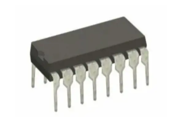
The 74190 is an integrated circuit (IC) called an up/down decade counter. It is used to count pulses or events in Binary Coded Decimal (BCD) format. The 74190 is an IC commonly used in various digital counting and control applications, including frequency division, event counting, and more.
It counts according to the positive edge clock signal in a synchronous manner, can realize rising and falling counting, has 4-bit output, and has mode control function to adapt to different counting requirements. Due to its characteristics, it is widely used in digital circuits and counting applications, including frequency division, event counting, timers, etc.
IC 74190 Specifications
Series: 74HC
Direction: Up, Down
Number of Elements: 1
Timing: Synchronous
Count Rate: 35 MHz
Voltage Supply: 2 V ~ 6 V
Mounting Type: Surface Mount
Trigger Type: Positive Edge
Number of Bits per Element: 4
Logic Type: Counter, Decade
Category: Integrated Circuits (ICs)
Supplier Device Package: 16-SO
Operating Temperature: -55°C ~ 125°C
Package / Case: 16-SOIC
IC 74190 Datasheet
IC 74190 Features
-
Synchronous Counter
"Synchronous" means that under the action of the clock signal, the state of the counter is updated synchronously. This means that the output of the counter is updated on the positive edge of the clock (i.e. a low-to-high transition). This way of updating makes it easy to cascade multiple counters, since they will be updated at the same time.
-
Positive Edge-Triggered
"Positive Edge-Triggered" means that the state of the counter is updated when triggered by the rising edge of the clock signal. This is a common trigger method, so that the update of the counter occurs at the moment the clock signal transitions from low level to high level.
-
4-Bit Counter
"4-Bit" means that the counter has 4-bit output, and each output represents a binary number. Therefore, the counter can count in the range of 0-15 (0000 to 1111 in binary).
-
Up/Down Decade Counter
"Up/Down" indicates that the counter can count up and down. "Decade Counter" means that the counter is a decimal counter that can count ten numbers from 0 to 9.
-
Mode Control
"Mode Control" indicates that the counter has a programmable mode control function. This may include different counting modes such as continuous up count, continuous down count, alternating up and down count, etc. Mode control allows selection of the appropriate counting mode according to the needs of the application.
-
Decade Counter
The 74190 is a decade counter, which means it can count from 0 to 9 in binary or BCD representation. It has four output pins, each representing a binary digit. These pins are usually labeled QA, QB, QC, and QD.
-
Up/Down Counting
The 74190 can count both up and down. The direction of counting is determined by the control inputs. When the appropriate control input is activated, the counter will either increment or decrement its count based on the clock pulses it receives.
-
Clock Input
The counter uses a clock signal to advance its count. Each clock pulse causes the counter to move to the next count. The clock input is typically labeled "CLK."
-
Control Inputs
There are two control inputs that determine the counting direction:
UP/DOWN (UD): When this input is low (0), the counter counts up. When it's high (1), the counter counts down.
ENABLE (EN): This input is used to enable or disable the counting action. When the enable input is high, the counter is enabled and will count as per the clock and direction inputs. When the enable input is low, the counter is disabled and won't change its count.
-
Parallel Load (PL) Input
This input allows you to directly load a BCD value into the counter. When the parallel load input is activated, the counter will load the BCD value provided on the data inputs.
-
Ripple Carry Output
The 74190 usually features a ripple carry output (RCO) that can be connected to the clock input of another counter. This is useful for cascading multiple counters to count beyond a single decade (0-9) range.
-
BCD Output
The output pins QA, QB, QC, and QD represent the BCD value of the current count. These pins are usually connected to other components, such as display drivers or further logic, to display or process the count.
74190 IC Applications
The 74190 IC, being a versatile up/down decade counter with mode control, finds applications in various digital and counting-related scenarios. Here are some common applications of the 74190 IC:
Frequency Division: One of the fundamental uses of the 74190 IC is frequency division. By counting clock pulses and generating specific count values on its outputs, the IC can divide an input frequency by a factor of 10 or any other desired value, which is useful for creating lower-frequency clock signals for different parts of a circuit.
Event Counting: The 74190 can be employed to count events or occurrences in a system. This can include monitoring the number of times a specific event happens, such as the number of cars passing through a toll booth, the number of products on a conveyor belt, or the number of times a button is pressed.
Digital Timers: The 74190 can serve as a building block for digital timers. By selecting appropriate counting modes and clock sources, it's possible to design timers that trigger certain actions after a predetermined time interval. For instance, in industrial applications, it could be used to control the duration of a machine operation.
Scoreboards and Displays: In games, sports scoreboards, and other applications where numeric displays are used, the 74190 IC can help manage and display scores, counts, or timings. Its outputs can be connected to display drivers or segment displays to show the current count.
Frequency Synthesis: The IC can be employed in frequency synthesizers to generate various output frequencies by selecting appropriate count values and clock sources. This is useful in communication systems and signal generators.
Digital Control and Sequencing: The ability to count up and down makes the 74190 suitable for creating digital control sequences. For example, it could be used to control the sequence of steps in a manufacturing process.
Educational Demonstrations: The 74190 IC is a popular choice for educational purposes. It can be used to teach concepts of binary counting, BCD representation, and sequential logic.
Cascade Counting: Multiple 74190 ICs can be cascaded together to create larger counting ranges. This is achieved by connecting the ripple carry output (RCO) of one counter to the clock input of another counter.
Industrial Automation: In various industrial settings, the IC can be employed for tasks such as counting products on an assembly line, monitoring the number of times a sensor is triggered, or controlling machinery based on specific counts.
Digital Control Systems: The 74190 can play a role in digital control systems where certain actions are triggered based on specific counts. This could be used in robotic systems, home automation, and more.
74190 IC Pinout

|
Pin |
Name |
Description |
|
1 |
UD (Up/Down) |
When LOW, the counter counts up; when HIGH, the counter counts down. |
|
2 |
CLK (Clock) |
The counter advances on the rising edge of the clock signal. |
|
3 |
PL (Parallel Load) |
Loads the BCD value from A, B, C, and D inputs when LOW and EN is HIGH. |
|
4 |
GND (Ground) |
Ground (0V) connection. |
|
5-8 |
NC (No Connect) |
Pins are not internally connected; left unconnected. |
|
11-14 |
QA, QB, QC, QD |
Outputs representing the binary-coded decimal (BCD) value of the current count. |
|
10 |
ENABLE (EN) |
When HIGH, enables the counter to respond to clock and control inputs. When LOW, the counter is disabled. |
|
15 |
RCO (Ripple Carry Output) |
Generates a pulse on overflow (9 to 0) for cascading counters. Used as the clock input for another counter. |
|
16 |
Vcc (Supply Voltage) |
Positive supply voltage input, typically connected to +5V. |
IC 74190 Working

The IC 74190 is a decade counter with up/down functionality. Overall, the IC 74190's working principle revolves around clock pulses, counting direction, and control inputs. It's a versatile counter IC used in a variety of applications requiring counting and control functions.
Initialization: Initially, the counter is set to a specific count value. This can be done using the parallel load (PL) input and providing the desired BCD value on the input pins QA, QB, QC, and QD. The ENABLE (EN) input should be high to allow the counter to respond to inputs.
Clock Pulse: The counter advances its count on the rising edge of the clock signal (CLK). The clock pulse can be manually generated or provided by an external source. When the clock pulse arrives, the counter updates its output based on the following conditions:
If the ENABLE input (EN) is high, the counter will respond to the clock pulse.
The counting direction (up or down) is determined by the state of the UP/DOWN (UD) input:
If UD is low, the counter will increment (count up) by 1 on each clock pulse.
If UD is high, the counter will decrement (count down) by 1 on each clock pulse.
Overflow and Ripple Carry: When the counter reaches the count of 9 (binary 1001) and an increment operation is performed, it overflows to 0 (binary 0000). This overflow is detected, and a ripple carry output (RCO) pulse is generated. The RCO can be used to cascade multiple counters, allowing for counting beyond a single decade.
Parallel Load Operation: If the parallel load (PL) input is low and the ENABLE (EN) input is high, the counter will load the BCD value present on the QA, QB, QC, and QD input pins on the next clock pulse.
Display and Further Processing: The BCD values on the output pins (QA, QB, QC, QD) can be used for various purposes, such as driving displays to show the current count. Additional logic can be connected to these outputs to implement specific control functions or to further process the count.
Enable/Disable: The ENABLE (EN) input controls whether the counter responds to clock pulses. When EN is high, the counter functions as described above. When EN is low, the counter is disabled and won't change its count, regardless of clock pulses or control inputs.
Read More:
CD4017BE CMOS Counter: Circuit, Pinout and Uses [Datasheet PDF]
IC 74192 UP/Down Counter Datasheet PDF, Circuit, Pin Diagram
IC 7490 Decade Counter Datasheet: Features, Pinout, Circuit and Working
What is Integrated Circuit Design?- How to Design?
Hybrid Integrated Circuits (Hybrid IC): Definition, Examples, Uses & Advantages
How Is a Microprocessor Different From an Integrated Circuit
Popular Blogs
-
![CD4440 IC: Datasheet, Amplifier Circuit Diagram, Pinout]()
CD4440 IC: Datasheet...
The CD4440 IC is a stereo audio power amplifier ...
-
![Small Outline Package (SOP): Definition, Applications and Advantages]()
Small Outline Packag...
SOP (Small Outline Package) is a type of integra...
-
![Advantages and Disadvantages of Operational Amplifier (Op-amp)]()
Advantages and Disad...
Operational amplifiers, or op-amps, offer a host...
-
![IC 74192 UP/Down Counter Datasheet PDF, Circuit, Pin Diagram]()
IC 74192 UP/Down Cou...
The 74192 is a versatile 4-bit synchronous up/do...
Hot Products


Popular Manufacturers