

IC 7490 Decade Counter Datasheet: Features, Pinout, Circuit and Working
Update Time: Oct 25, 2023 Readership: 3208
Contents
The IC 7490, often referred to as a "Decade Counter," is an integrated circuit used in digital electronics for counting and sequencing purposes. Developed as a monolithic device, the IC 7490 contains a combination of flip-flops and digital logic gates that allow it to count in a variety of ways. This versatile IC has found applications in numerous electronic systems and is especially useful in digital counting, frequency division, and timing applications.
Specification
|
Specification |
Description |
|
Counting Modes |
Divide-by-Two, Three-Stage Binary |
|
Gated Inputs |
Gated Zero Reset, Gated Set-to-Nine |
|
Power Dissipation |
Typical: 145 mW |
|
Count Frequency |
Up to 42 MHz |
|
Decoding Type |
Binary-Coded Decimal (BCD) and Binary |
|
Number of Flip-Flops |
4 |
|
Counting Range |
0 to 9 in BCD Mode, 0 to 7 in Binary Mode |
|
Monolithic Design |
Yes |
|
Commonly Used in |
Digital counting, frequency division, timing applications |
|
Package Type |
DIP (Dual In-line Package) and others |
Read more: IC 7490 Datasheet
Features of IC 7490
-
Decade Counter
The primary function of the IC 7490 is to count in decimal (0-9) sequence. It has four internal flip-flops that enable it to count in a decade sequence, making it suitable for various counting applications.
-
Two Counting Modes
It can function as a simple divide-by-two counter, where it toggles between two states, effectively dividing the input frequency by 2. It can also operate as a three-stage binary counter, allowing it to count through eight binary states (000 to 111), with the count cycle length being divide-by-five. This is useful for applications where you need more complex counting sequences.
-
Gated Zero Reset
The IC 7490 features a gated zero reset input. When this input is activated, the counter is reset to zero, allowing you to start counting from the beginning. This is useful for applications where you need to initiate counting from a specific point.
-
Gated Set-to-Nine Inputs
This feature is particularly useful for Binary-Coded Decimal (BCD) nine's complement applications. It allows you to set the counter to nine (1001 in binary) under certain conditions, which is helpful in BCD arithmetic.
-
Low Power Consumption
The IC 7490 typically consumes relatively low power, with a typical power dissipation of around 145 mW. This makes it energy-efficient for various applications.
-
High Count Frequency
It is capable of handling count frequencies up to 42 MHz. This means it can count events at a very high rate, making it suitable for high-speed applications.
-
Monolithic Design
The IC 7490 is a monolithic design, which means all of its components are integrated into a single chip, simplifying its use and connection in digital circuits.
IC 7490 Manufacturer
Fairchild Semiconductor, established in the late 1950s, stands as a pioneering force in the semiconductor industry. It gained distinction for its trailblazing contributions, including the development of the first commercial transistor and its substantial role in advancing integrated circuit technology. Fairchild solidified its position as a prominent supplier, specializing in power semiconductors, analog and mixed-signal integrated circuits, and an array of semiconductor products. In 2016, Fairchild was acquired by ON Semiconductor, and today, its innovative products and technologies persist under the ON Semiconductor brand, carrying on the legacy of innovation and excellence.
Decade Counter Using IC 7490
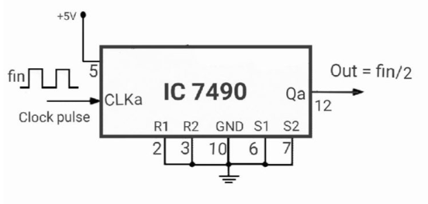
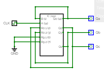
MOD-2 Counter Using IC 7490
MOD-6 Counter Using IC 7490
Read more: How do I Make a Mod 6 Counter by Using a 7490 IC Chip
MOD-7 Counter Using IC 7490
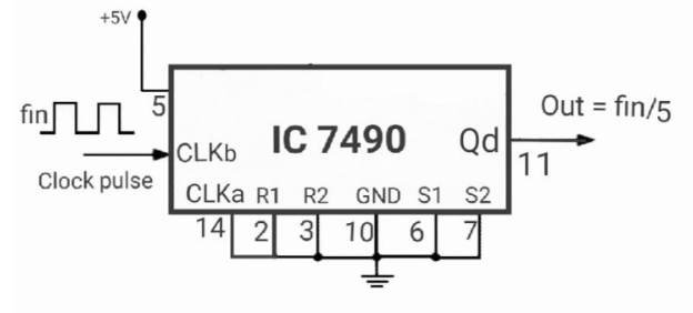
MOD-5 Counter Using IC 7490
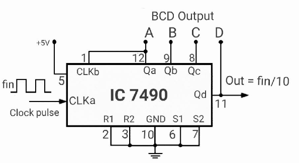
MOD-10 Counter Using IC 7490
MOD-100 Counter Using IC 7490
IC 7490 Working
-
Counting Modes
In BCD mode, the IC counts from 0 to 9 in binary-coded decimal format. The BCD format represents each decimal digit using a 4-bit binary code. The IC 7490 counts in the following sequence: 0000, 0001, 0010, 0011, 0100, 0101, 0110, 0111, 1000, 1001 (0 to 9 in decimal).
In binary mode, the IC counts from 0 to 7 in straight binary. The binary format uses 3 bits to represent numbers. The IC 7490 counts in the following sequence: 000, 001, 010, 011, 100, 101, 110, 111 (0 to 7 in decimal).
-
Clock Input (CP)
The IC 7490 counts based on clock pulses applied to its CP pin. Each rising or falling edge of the clock input triggers the counter to advance to the next count in the sequence.
-
Gated Inputs
Gated Zero Reset (MR): When a signal is applied to the MR (Master Reset) input, it resets the counter to 0 (0000 in BCD or 000 in binary), regardless of the current count.
Gated Set-to-Nine (DCBA): The DCBA inputs allow you to preset the counter to any value between 0 (0000 or 000) and 9 (1001 or 100) in BCD or 7 (0111 or 111) in binary. These inputs are typically used in BCD arithmetic and other applications where you need to set the counter to a specific value.
-
Outputs
The IC 7490 has four outputs labeled as A, B, C, and D. These outputs represent the current count in binary form. In BCD mode, they indicate the BCD code for the count (0 to 9).
-
Ripple-Carry Output (RCO)
The IC 7490 has a carry-out (RCO) pin that produces a carry signal when the counter advances from 9 (1001 in BCD) to 0 (0000 in BCD). This carry signal can be used to cascade multiple IC 7490s for counting beyond 9.
-
Decoding Logic
The internal decoding logic is responsible for generating the appropriate BCD or binary count sequence and controlling the carry signal when the counter wraps around.
7490 IC Pinout
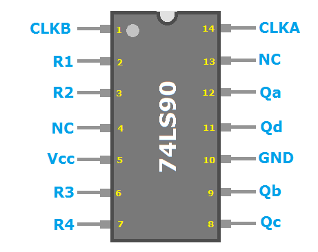
IC 7490 pin diagram
|
Pin No. |
Pin Name |
Description |
|
1 |
CLKB |
Clock Input (There are two clock input pins) |
|
2 |
R1 |
Reset Pin (Resets the circuit to start counting again) |
|
3 |
R2 |
Reset Pin |
|
4 |
NC |
Not connected to the circuit |
|
5 |
Vcc |
Positive Power Supply Pin |
|
6 |
R3 |
Reset Pin |
|
7 |
R4 |
Reset Pin |
|
8 |
Qc |
Output Pin 3 |
|
9 |
Qb |
Output Pin 2 |
|
10 |
GND |
Negative Power Supply Pin |
|
11 |
Qd |
Output Pin 4 |
|
12 |
Qa |
Output Pin 1 |
|
13 |
NC |
Not connected to the Circuit |
|
14 |
Clock input pin 1 |
Clock Input (There are two clock input pins) |
7490 IC pin configuration
Application of IC 7490
The IC 7490, a decade counter with versatile counting modes, reset options, and clock inputs, finds applications in various digital electronic systems.
-
Frequency Division
The IC 7490 is often used to divide an input frequency by a factor of 2 or 5, depending on the selected counting mode. This is useful for generating lower-frequency clock signals from a higher-frequency source, helping in synchronization and timing in digital circuits.
-
Event Counting
It's employed for counting events, pulses, or occurrences in various applications. For example, in industrial automation, it can be used to count products on a conveyor belt or machine cycles.
-
Digital Clocks
In digital clock circuits, the IC 7490 can be used to generate BCD digits for hours, minutes, and seconds. It helps in timekeeping and displaying the current time.
-
Frequency Divider
In signal processing, the IC 7490 can serve as a frequency divider, allowing you to work with signals at a lower frequency, which simplifies signal processing and analysis.
-
BCD Arithmetic
It's used in BCD arithmetic operations, especially when the need arises to perform addition and subtraction in BCD format, such as in calculators and digital displays.
-
Sequencing
The IC 7490 can be used to control sequencing in various applications. For example, it can be used in sequential control systems where different states need to be cycled through.
-
Digital Counters
It's often used as a building block for more complex digital counter circuits. By cascading multiple IC 7490s, you can create counters with higher count ranges.
-
Educational Purposes
The IC 7490 is commonly used in educational settings to teach digital electronics, digital logic, and counting concepts.
-
Automated Testing
It can be used in test equipment and automated testing systems where the counting and sequencing of test signals or events are required.
-
Synchronization
It's employed in various applications that require synchronization, such as controlling the timing of data transfer or processing in digital systems.
-
Traffic Light Control
In traffic light control systems, the IC 7490 can be used to sequence the lights through their different states (red, yellow, green) at specific time intervals.
-
Pulse Generation
It can be used to generate specific pulse patterns for various applications, including waveform generation in electronic music.
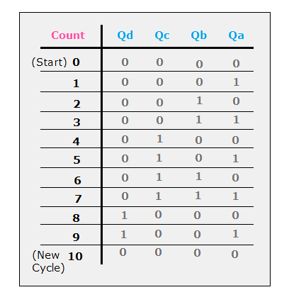
IC 7490 Truth Table
After counting from zero to nine, it gracefully resets itself, commencing the counting cycle anew. This characteristic makes it a versatile and valuable component in digital circuitry, especially when the need arises for cyclic counting from 0 to 9.
Difference Between IC 7490 and IC 7493
The primary difference between the 7490 and 7493 is in the counting mode or the number of states they can traverse.
The 7490 is a decade counter, which means it can count from 0 to 9 in binary-coded decimal (BCD) format before resetting to 0. It can traverse 10 states: 0000 to 1001 (in binary). In BCD mode, it counts from 0 to 9, and in binary mode, it counts from 0 to 7.
The 7493 is a 4-bit binary counter that can count from 0 to 15 (in binary) before resetting to 0. It can traverse 16 states: 0000 to 1111 (in binary). It's often used in applications where a wider count range is needed compared to the 7490.
In summary, the primary difference is in the maximum count range. The 7490 is a MOD-10 counter, and the 7493 is a MOD-16 counter, meaning the 7493 can count through 16 states while the 7490 counts through 10 states before resetting. These ICs are chosen based on the specific counting requirements of the electronic circuit or system in which they are used.
7490 IC Circuit
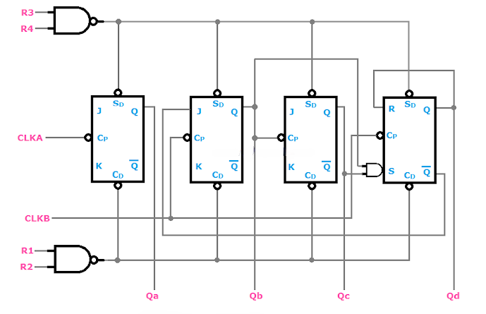
IC 7490 Internal Circuit
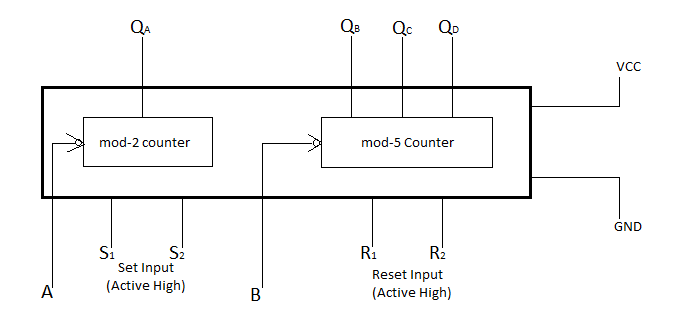
Block Diagram
-
Power Supply (VCC and GND)
VCC and GND serve as the vital power supply input pins for the IC 7490. These pins are essential in providing the necessary electrical power to the integrated circuit. These input terminals are ubiquitous in electronic devices to ensure they receive the required power. VCC, an acronym for Voltage Common Collectors, typically signifies a higher voltage level concerning the GND (Ground) terminal. The voltage can be either positive or negative concerning the GND.
-
Clock Inputs (A and B)
The pins denoted as A and B in the diagram are referred to as Clock Inputs. These input terminals are instrumental in furnishing clock signals to the IC. Clock inputs are a common feature in most counter ICs and serve the purpose of timing and synchronizing the counting process.
-
Set Inputs (S1 and S2)
S1 and S2 are the designated Set Input terminals. They enable the configuration or "setting" of specific data or states within the IC. For instance, you can load a particular state, such as 0011 (representing 3 in binary), using these inputs. If the intention is to initiate counting from the initial state, 0000 (denoting 0), these Set Inputs need to be connected to VCC or logic high (1). The Set Inputs play a pivotal role in instructing the IC to commence counting from the specified state. In the case of IC 7490, it typically initiates counting from 0000 (0) by default since it lacks a pre-set input. Therefore, to maintain this default behavior, the Set Inputs (S1 and S2) are generally connected to GND (Ground).
Counter Designing using 7490 IC
When delving into the realm of Counter ICs, it's important to grasp some fundamental terminology that will frequently come into play during the design process. Understanding these terms is essential for designing effective counters.
-
Asynchronous Counters
In Counter ICs, you'll encounter multiple Clock Inputs that correspond to the internal structure of Flip-Flops. When the Clock Inputs of these Flip-Flops are not controlled by the same Clock Signals (Pulses), the counter is termed an Asynchronous Counter. Prominent examples of Asynchronous Counters include ICs 7490 and ICs 7493.
-
Synchronous Counters
Conversely, in Synchronous Counters, the Clock Inputs of all the Flip-Flops are steered by the same Clock Signals (Pulses). This synchronization defines Synchronous Counters. Notable examples encompass ICs 74160, ICs 74163, ICs 74168, and ICs 74169.
-
Clock Signals (Pulses)
Clock Signals are continuous high-low waveforms, often represented as square waveforms, crucial for the proper functioning of counters.
-
BCD (Binary Coded Decimal)
BCD stands for Binary Coded Decimal. It involves replacing decimal numbers with their equivalent binary codes. For example, the decimal number 10 is represented by its binary counterpart 1010.
-
Mod-n
"Mod" represents the modulus of the counter, with "n" being an integer. The Modulus of the Counter denotes the total number of unique states it should pass through in a single complete counting cycle. In practical terms, if you wish to design a mod-6 counter, it must navigate through six unique states in a full counting cycle. These states are 0000 (0), 0001 (1), 0010 (2), 0011 (3), 0100 (4), and 0101 (5), before returning to 0000 (0).
-
Frequency Division
Every counter circuit is constructed using Flip-Flops, and for the output of such a sequential circuit to undergo a frequency division, it's essential for common Clock Signals to trigger the Clock Inputs of all Flip-Flops. In doing so, the resulting output frequency is consistently reduced by 50% from the previous cycle. The figure provided below elucidates this concept, making it clear how Frequency Division operates. Notably, the IC 7490 can serve as a proficient frequency divider circuit, capable of dividing the input frequency by factors of 2, 5, and 10.
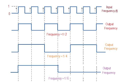
Frequency Division
-
Sequential Circuits
Sequential circuits are those where the count progresses in a systematic order, either increasing or decreasing. One of the illustrative examples of a sequential circuit is the IC 7490, a decade counter. The IC 7490 follows a sequential counting pattern, specifically 0, 1, 2, 3, 4, 5, 6, 7, 8, 9. Its counting sequence ascends in an upward direction, making it commonly referred to as an "Up Counter."
Read More:
What is Integrated Circuit Design?- How to Design?
Hybrid Integrated Circuits (Hybrid IC): Definition, Examples, Uses & Advantages
How Is a Microprocessor Different From an Integrated Circuit
Small Outline Integrated Circuit - SOIC
Different Types of IC [Integrated Circuit]
IC 74190 Datasheet, Working, Features, Application
CD4017BE CMOS Counter: Circuit, Pinout and Uses [Datasheet PDF]
IC 74192 UP/Down Counter Datasheet PDF, Circuit, Pin Diagram
Extended Reading
 FAQ
FAQ
-
What is the function of IC 7490?
The IC 7490 serves the purpose of counting binary numbers, encompassing the range from 0000 to 1001. Once it reaches the count of 1001, it automatically resets itself, initiating the counting cycle anew. This unique attribute of resetting after tallying ten numbers earns the IC 7490 its title as a MOD-10 Decade Counter.
-
What is 7490 IC?
The IC 7490 is a 4-bit decade counter featuring four master/slave flip-flops intricately interconnected to create two essential sections: a divide-by-two segment and a divide-by-five section. For seamless operation, each section is endowed with its dedicated clock input, facilitating the transformation of output states with precision upon a high-to-low clock transition.
-
How do I reset my 7490 IC?
The IC 7490 employs a modular approach to counting, and this modulus, or Mod, can be configured by manipulating the RESET pins R1, R2, R3, and R4. In this system, the behavior is determined by the combinations of these pins. When either R1 or R2 is set to a high state, or if R3 and R4 are grounded, the counter will systematically reset all of its outputs, namely QA, QB, QC, and QD, to zero. On the other hand, when R3 and R4 are both in a high state, the counter's output takes on the value 1001. These precise combinations of RESET pins allow for control and adjustment of the counting process within the IC 7490.
-
How to use 7490?
To utilize the 7490 as a counter effectively, provide +5V power on pin 5, establish a ground connection on pin 10, introduce the input pulse train on pin 14, connect pin 12 to pin 1 for decade counting, and ground pins 3 and 6 to enable smooth counting operations.
-
What is a decade counter used for?
Clock circuits, state machines, frequency dividers, and sequencers.
-
What is the difference between 4017 and 7490?
A 7490 operates as a Binary-Coded Decimal (BCD) counter, capable of counting from 0 to 9 in binary representation. In contrast, a 4017 exhibits a different functionality with its 10 outputs, each sequentially corresponding to a specific number, one output per number. These two ICs are not closely similar.
-
What is a decade counter also known as?
Modulo-10 Counter.
Popular Blogs
-
Small Outline Packag...
SOP (Small Outline Package) is a type of integra...
-
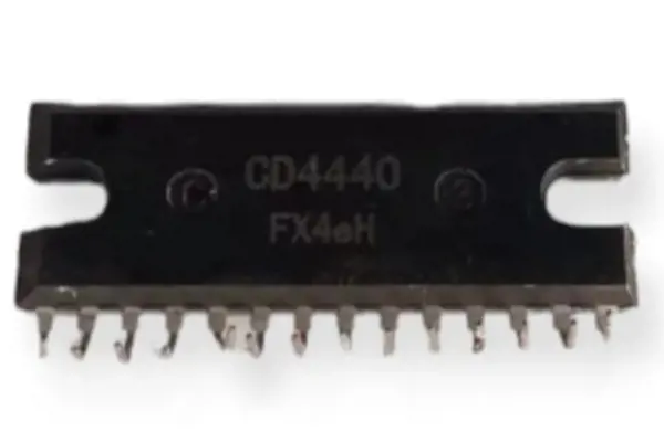
CD4440 IC: Datasheet...
The CD4440 IC is a stereo audio power amplifier ...
-
Advantages and Disad...
Operational amplifiers, or op-amps, offer a host...
-
Dual Inline Package ...
Dual in-line package, also known as DIP package ...
Hot Products
-
-

-
-
-
-
-
-
-
-
-
-
-
-
-
-
-
-
-
-
-
-
-
-
-
-
-
-
Infineon Technologies Corporation
100V Single N-Channel HEXFET Power MOSFET in a PQF...
-
Infineon Technologies Corporation
100V Single N-Channel HEXFET Power MOSFET in a D2-...
-
Infineon Technologies Corporation
150V Single N-Channel HEXFET Power MOSFET in a 5mm...
-
Infineon Technologies Corporation
150V Single N-Channel HEXFET Power MOSFET in a D2-...
-
Infineon Technologies Corporation
200V Single N-Channel HEXFET Power MOSFET in a D2-...
-

-
Infineon Technologies Corporation
250V Single N-Channel HEXFET Power MOSFET PDP Swit...
-
-
-
-
-
Infineon Technologies Corporation
60V Single N-Channel HEXFET Power MOSFET in a PQFN...
-
Infineon Technologies Corporation
A 30V Single N-Channel HEXFET Power MOSFET in a Di...
-
-
-
-
-
-
-
-
-
-
Popular Manufacturers