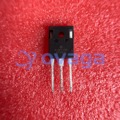
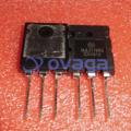
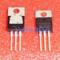
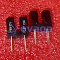
A1015 Datasheet, Equivalent, Pinout, Circuit, Uses
Update Time: Oct 20, 2023 Readership: 9503
Contents
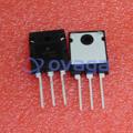
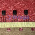
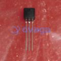
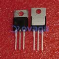
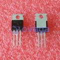
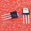
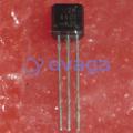
The A1015 is a widely used PNP (Positive-Negative-Positive) transistor with a general-purpose design. Its popularity stems from its reliability and versatility, particularly in low-power and low-voltage applications. This article provides a detailed look at the features, pinout, typical uses, specifications, and other important details about the A1015 transistor.
Specification and Features
|
Characteristic |
Value/Range |
|
Type |
PNP |
|
Maximum Collector Power Dissipation (Pc) |
0.4 W (Watts) |
|
High Voltage and High Current |
Vceo = 50V, Ic = 150mA |
|
Low Noise |
1 dB |
|
Case Material |
Molded Plastic |
|
DC Current Gain (hfe) |
70 to 400 |
|
Collector-Base Voltage (Vcb) |
-50 V |
|
Collector-Emitter Voltage (Vce) |
-50 V |
|
Emitter-Base Voltage (Veb) |
-5 V |
|
Maximum Collector Current (Ic max) |
-150 mA |
|
Max. Operating Junction Temperature (Tj) |
150 °C |
|
Transition Frequency (ft) |
80 MHz |
|
Complementary Transistor |
2SC1815 |
2D-Model
Absolute Maximum Ratings (at Ta = 25°C)
|
Characteristic |
Symbol |
Rating |
Unit |
|
Collector-Base Voltage (VCBO) |
VCBO |
-50V |
Volts |
|
Collector-Emitter Voltage (VCEO) |
VCEO |
-50V |
Volts |
|
Emitter-Base Voltage (VEBO) |
VEBO |
-5V |
Volts |
|
Collector Current (IC) |
IC |
-150mA |
Milliamperes |
|
Power Dissipation (PC) |
PC |
400mW |
Milliwatts |
|
Junction Temperature (Tj) |
Tj |
150°C |
Celsius |
A1015 Transistor Equivalent/Replacement/Alternative
The list of equivalent transistors includes a variety of PNP transistors with different electrical characteristics. To find an appropriate replacement for the A1015, you should indeed cross-verify and select a replacement that closely matches the original transistor's specifications.
|
Part Number |
Manufacturer |
Description |
|
NTE290A |
NTE Electronics |
Silicon NPN Transistor with high current and voltage ratings. Commonly used for amplification in various electronic circuits. |
|
2SA495 |
Various |
Silicon PNP Transistor designed for high-frequency applications. |
|
2SA561 |
Various |
Silicon PNP Transistor used in low-power amplification and switching applications. |
|
2SA564A |
Various |
Silicon PNP Transistor often used in low-power and low-frequency applications. |
|
2SA573 |
Various |
Silicon PNP Transistor used in low-power and low-frequency signal amplification. |
|
2SA675 |
Various |
Silicon PNP Transistor used in low-frequency amplification and switching applications. |
|
2SA705 |
Various |
Silicon PNP Transistor suitable for low-frequency amplification and switching tasks. |
|
2SA850 |
Various |
Silicon PNP Transistor typically used in low-power applications. |
|
2SA999 |
Various |
Silicon PNP Transistor designed for low-frequency amplification. |
|
KTA1015 |
Fairchild Semiconductor |
Silicon PNP Transistor, often used in low-power amplification and switching applications. |
|
BC212 |
Various |
Silicon PNP Transistor with applications in low-power amplification. |
|
BC257 |
Various |
Silicon PNP Transistor suitable for low-power applications. |
|
BC307 |
Various |
Silicon PNP Transistor used in low-power amplification and switching applications. |
|
BC557 |
Various |
Silicon PNP Transistor frequently used in low-power signal amplification. |
|
2N3494 |
Various |
Silicon PNP Transistor designed for general-purpose applications. |
|
2SA781 |
Various |
Silicon PNP Transistor often employed for low-frequency signal amplification. |
|
KT3108A |
Fairchild Semiconductor |
Silicon PNP Transistor suitable for low-power amplification and switching applications. |
|
2SA1015 |
Various |
Silicon PNP Transistor typically used for low-frequency signal amplification. |
|
2SA1267 |
Various |
Silicon PNP Transistor commonly used in low-frequency applications. |
|
2SB560 |
Various |
Silicon PNP Transistor often used in low-power and low-frequency signal amplification. |
|
KSA1015 |
Fairchild Semiconductor |
Silicon PNP Transistor suitable for low-frequency amplification and switching tasks. |
|
KTA1266 |
Fairchild Semiconductor |
Silicon PNP Transistor frequently used in low-power amplification and switching applications. |
A1015 Pinout
Equivalent Circuit
A1015 Transistor Pinout Description:
-
Emitter (E)
Pin Number: 1
Description: The emitter is the terminal through which the transistor's collector current exits. It is also the lead through which current flows into the transistor when it's in the active state. In PNP transistors like the A1015, the emitter is typically connected to the most negative voltage level (negative with respect to the collector) in the circuit. Current flows from the emitter to the collector when the transistor is in its active mode.
-
Collector (C)
Pin Number: 2
Description: The collector is where the transistor's collector current enters the device. It plays a crucial role in controlling the flow of current between the emitter and collector. The collector is typically connected to the positive supply voltage in PNP transistors. When the base current is applied to the transistor, it allows current to flow from the emitter to the collector, thus amplifying or switching the input signal.
-
Base (B)
Pin Number: 3
Description: The base terminal is responsible for controlling the transistor's operation. When a small current is applied to the base, it regulates the much larger current flowing from the emitter to the collector. By controlling the base current, you can switch the transistor between its "off" and "on" states. In amplification applications, a small change in the base current results in a much larger change in collector current, making the transistor suitable for signal amplification.
A1015 Transistor Circuit Diagram
-
A1015 Transistor Amplifier
The diagram illustrates an amplifier circuit using A1015 and C1815 transistors.
This is a push-pull AB class amplification circuit composed of two transistors as amplifying components and two antiparallel diodes to achieve complementary operation.
When an audio signal is fed into the circuit, it is initially bypassed by an input capacitor. Subsequently, the signal undergoes amplification through the two transistors. The push-pull operation of A1015 and C1815 transistors results in a substantial amplification of the audio signal, taking into account the signal's characteristics.
-
LED flasher using 2SA1015
In the circuit illustrated below, we've employed a 2SA1015 transistor in an LED flasher application. Here's how it operates:
Capacitor C1 and resistor R1 work in tandem to generate a specific frequency, which is then supplied to the base of transistor Q1. Q1 serves as a switch that controls the behavior of Q2. Q2, in turn, is responsible for amplifying the current. The process unfolds as follows:
Initially, the voltage builds up across C1. During this phase, Q1 remains active, facilitating the flow of current through R2 and the LED. As the voltage across C1 continues to rise, it eventually reaches a point where Q2 starts to conduct. At this juncture, a current begins to flow through the LED, causing it to illuminate.
As C1 gradually discharges through R1 over a specified period, it reaches a point where it can no longer provide bias to the base terminal of Q1. Consequently, Q1 ceases to function, leading to the deactivation of Q2. This, in turn, causes the LED to switch off.
With the LED turned off, C1 begins the process anew, setting off a continuous cycle. This on-off sequence of the LED creates the flashing effect, making it appear as a flasher.
A1015 Transistor Uses
A1015 transistor serves a dual purpose as both an audio amplifier and a versatile switch in electronic circuits. Whether enhancing sound quality or providing precise control over electronic components, the A1015 transistor plays a vital role in modern electronic design.
A1015 transistors are commonly employed in audio amplifiers to boost the strength and clarity of audio signals. They can be used as small audio amplifiers in devices like doorbells, MP3 players, radios, and more. This application ensures that even weak audio signals are delivered with increased volume and fidelity.
A1015 transistors are frequently integrated into the various stages of audio amplifier circuits. These stages include pre-amplification, power amplification, and output stages. By using A1015 transistors, these amplifier circuits can effectively process and boost audio signals throughout the system.
Beyond audio amplification, A1015 transistors exhibit remarkable versatility in switching applications. A1015 transistors effectively manage electromagnetic relays, enabling them to switch high-power loads such as lighting systems and motors. These transistors act as reliable drivers for light-emitting diodes (LEDs) used in applications like indicator lights and displays.
A1015 CAD Model
Symbol
Footprint
3D Model
A1015 Transistor Application
-
Audio Amplification
The A1015 transistor is commonly used in audio amplifier circuits, including audio preamplifiers, amplifier stages, and audio frequency circuits. It enhances the clarity and strength of audio signals, making it suitable for devices like radios, MP3 players, and doorbells.
-
Switching Loads
A1015 transistors are versatile in switching applications, particularly for loads under 150mA. They can act as switches in various electronic circuits, controlling components such as relays, LEDs, and high-power transistors. This makes them valuable in switching circuits and driver stage amplifier actions.
-
Darlington Pair
A1015 transistors can be configured as a Darlington pair, which is a high-gain configuration of two transistors in series. This setup is excellent for applications requiring high current gain and precise control.
-
LED Flasher
A1015 transistors are utilized in LED flasher circuits. They contribute to the on-off cycling of LEDs, creating a flashing effect commonly seen in indicator lights and other applications.
-
Water Level Indicator
These transistors play a role in water level indicator circuits, where they help detect and indicate water levels in tanks or reservoirs.
-
Driver Circuits
A1015 transistors are employed as drivers in various electronic circuits. They facilitate the control and operation of other components, including integrated circuits (ICs).
Electrical Characteristics
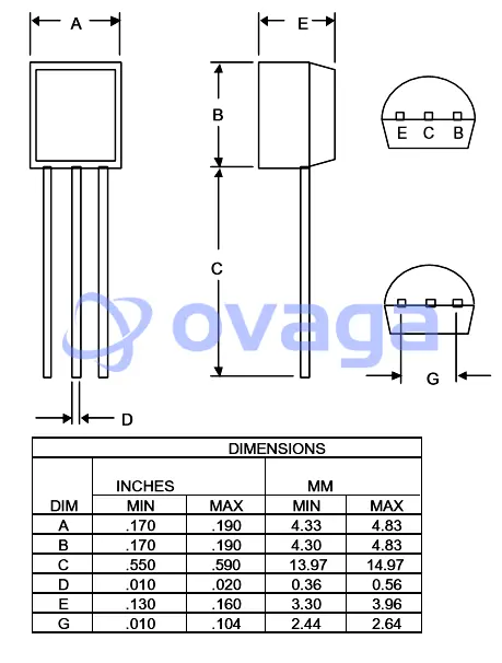
A1015 Package
Read More:
C1815 Transistor Datasheet, Pinout, Equivalent, Voltage, Circuit and Uses
C945 Transistor Datasheet, Pinout, Equivalent and Uses
D882 Transistor Pinout, Equivalent, Uses and Datasheet
What is Transistor hFE
13003/MJE13003 Transistor: Pinout, Features, Equivalent and Uses
2N6027 Transistor Datasheet, Pinout, Equivalent and Uses
S9012 Transistor Datasheet, Pinout, Equivalent and Uses
Previous:Gain of an Instrumentation Amplifier
Next:LT1028 vs OPA627
Extended Reading
 FAQ
FAQ
-
Should I use NPN or PNP
If you require high current handling, NPN transistors are preferable, while if you need lower turn-on voltage for high-speed applications, PNP transistors are more suitable.
-
Why is it called a PNP transistor
The nomenclature NPN stands for Negative-Positive-Negative, symbolizing the arrangement of charge carriers, while PNP signifies Positive-Negative-Positive, reflecting the corresponding polarity.
-
Can a PNP transistor work as a switch
Yes, a PNP transistor can indeed function as a switch, similar to how an NPN transistor is used.
-
What is the difference between NPN and PNP transistors
NPN and PNP transistors represent two fundamental types of bipolar junction transistors with key distinctions in charge carriers and switching conventions. NPN transistors are electron-based, with the N-type material containing extra electrons and switching ON when a high voltage is applied to the base relative to the emitter. In contrast, PNP transistors rely on holes as the majority charge carriers, with the P-type material containing holes. They switch ON when a low voltage is applied to the base compared to the emitter.
-
How does a PNP transistor work
A PNP transistor operates by controlling the flow of current from the collector to the emitter using a small current applied to the base-emitter junction. The injection of electrons from the N-type base to the P-type emitter, and subsequent diffusion of electrons across the base, allows for current amplification and the transistor's switching capabilities.
-
What is the gain of A1015 transistor
The gain of the A1015 transistor, also known as its DC current gain (hfe or β), typically falls within the range of 70 to 400.
-
What is the voltage of A1015
The A1015 transistor is designed to handle voltages up to 50V. When fully biased, which typically requires a base-emitter voltage of about 1.1V, it can carry a collector current of up to 150mA. This means that the transistor is capable of switching loads with voltages up to 50V while controlling a maximum current of 150mA when properly configured in a circuit.
Popular Blogs
-
PCA9617ADPJ Datashee...
The PCA9617ADPJ is a signal buffer and repeater ...
-

D882 Transistor Pino...
The D882 transistor is a commonly used NPN bipol...
-

C1815 Transistor Dat...
The C1815 is a general purpose NPN transistor us...
-
C945 Transistor Data...
The C945 transistor is a small, low-power NPN bi...


