

Common Uses of Diodes in Circuit Design
Update Time: Feb 12, 2021 Readership: 2433
Contents
Reverse polarity protection
A diode in the main circuit is connected in series to utilize its unidirectional conductivity characteristic, providing a simple, reliable, low-cost reverse protection circuit. This low-cost solution is generally used in small current applications, such as small toys. A diode has a forward voltage drop of 0.7V (silicon diode), which can cause heat dissipation and heating when the current is large. If the reverse voltage is too high and exceeds the reverse breakdown voltage, the diode may fail, losing its reverse protection function and failing to protect the subsequent circuitry.
Rectification
The purpose of a rectification circuit is to convert the lower AC voltage output from an AC step-down circuit into a unidirectional pulsating DC voltage. Rectification circuits are primarily composed of rectifier diodes. After rectifying, the voltage is a mixture of DC and AC voltages, commonly called unidirectional pulsating DC voltage.
Voltage regulation
Diodes with voltage regulation functions are called voltage regulator diodes, also known as Zener diodes. They utilize the reverse breakdown state of the PN junction, where the current can change significantly while the voltage remains almost constant.
Freewheeling
Freewheeling diodes are connected in parallel across the coil (inductive component). When the coil is energized, an induced electromotive force (EMF) is generated across its ends. The induced EMF creates a reverse voltage across the circuit components when the current disappears. If the reverse voltage exceeds the reverse breakdown voltage of the component, such as a transistor, it can cause damage. The freewheeling diode connected in parallel across the coil dissipates the induced EMF through a closed loop, protecting the safety of other components in the circuit.
Detection
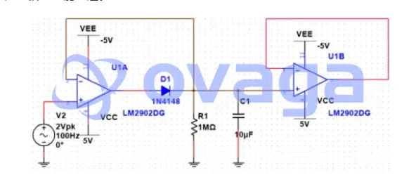
Peak detection circuits detect the maximum value of the input signal amplitude. When the input voltage amplitude is greater than the diode's forward voltage, the diode conducts, and the output voltage is charged across capacitor C1. When the input voltage amplitude is lower than the previously charged voltage, the diode is in reverse bias cutoff, and the capacitor voltage remains relatively constant. The diode will only conduct again if the input signal voltage amplitude exceeds the capacitor voltage across the diode.
Voltage multiplication
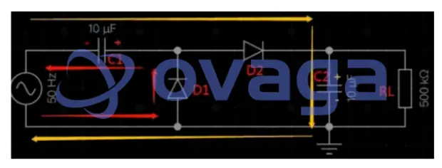
The following figure shows a 2x voltage multiplier circuit schematic. When the power supply is in the negative half-cycle, diode D1 conducts, and D2 is cut off, allowing current to flow from the lower end of the power supply through D1 and C1 back to the power supply. The voltage across capacitor C1 is positive on the right and negative on the left. During the positive half-cycle, the voltage across C1 is added to the power supply voltage, causing diode D2 to conduct and D1 to cut off. The voltage across capacitor C2 is positive on the top and negative on the bottom, with a peak value reaching twice the power supply peak voltage, achieving voltage doubling.
ADC input voltage clamping
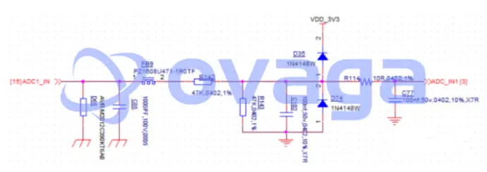
In some ADC detection circuits, two diodes are used for clamping protection. The principle is simple: 0.7V is the forward voltage drop of D1 and D2. When the incoming voltage Vin is greater than or equal to 3.3V + 0.7V, D35 conducts, and Vout is clamped at 4V. When Vin is less than or equal to -0.7V, Vout is clamped at around -0.7V.
Envelope detection
The circuit structure is shown below. The design principle is that the time constant of RC should be much larger than the carrier frequency period and much smaller than the modulation signal period. Envelope detection circuits extract the amplitude-modulated (AM) signal's envelope from a modulated carrier wave. In these circuits, the diode conducts when the input signal amplitude is greater than the diode's forward voltage, and the capacitor C1 charges to the peak value of the input waveform. The diode enters reverse-bias cutoff when the input signal amplitude is lower than the charged voltage across the capacitor.
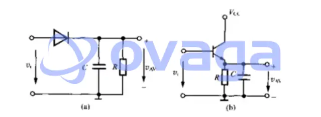
The capacitor voltage remains relatively constant, following the input signal's envelope. The resistor R helps discharge the capacitor, allowing the output voltage to track the input envelope accurately.
Extended Reading
- Exploring the Power and Precision of Brushless Motor Controllers
- How Electric Motors are Changing the Automotive Industry?
- Control Techniques for Electric Motors: Optimizing Performance and Efficiency
- Revolutionizing Electric Mobility: The Synergy of Cyberquad Motor Controller and Tesla's Innovation
 FAQ
FAQ
-
What is the purpose of a diode in a rectifier circuit?
In a rectifier circuit, diodes are used to convert alternating current (AC) to direct current (DC). Diodes allow current to flow only in one direction, which means they clip the negative or positive half of the AC waveform, depending on the diode's orientation. In a full-wave rectifier circuit, a combination of diodes is used to convert both the positive and negative half-cycles of the AC waveform into a pulsating DC output. This output can then be further filtered and regulated to obtain a smooth and stable DC voltage.
-
What is the difference between forward and reverse bias in a diode?
Forward bias occurs when the voltage applied across a diode causes the anode to be more positive than the cathode. In this condition, the diode conducts current as the electrons and holes combine at the p-n junction. Reverse bias occurs when the voltage applied across the diode causes the cathode to be more positive than the anode. In this condition, the diode does not conduct current (except for a small leakage current) as the electrons and holes are pushed away from the p-n junction.
-
How do diodes work?
Diodes work by taking advantage of the properties of semiconductor materials. They consist of a p-n junction, which is formed by joining a p-type semiconductor (having an excess of positively charged holes) with an n-type semiconductor (having an excess of negatively charged electrons). When a voltage is applied across the diode with the anode more positive than the cathode, the electrons and holes combine at the junction, allowing current to flow. However, if the voltage is reversed, the electrons and holes are pushed away from the junction, creating a barrier that prevents current flow.
-
What is a diode?
A diode is a semiconductor device that allows current to flow in one direction but not in the opposite direction. It consists of two terminals: the anode (positive) and the cathode (negative). Diodes are typically made from semiconductor materials like silicon or germanium and are widely used in electronic circuits for various purposes such as rectification, voltage regulation, and switching.
Popular Blogs
-
Exploring the Power ...
Brushless motor controllers are advanced electro...
-
How Electric Motors ...
With rapidly development in technology, electric...
-
Control Techniques f...
Discover how advanced motor control software, va...
-

Revolutionizing Elec...
Central to Tesla's success is its relentless pur...
Hot Products
-
-
-
-
-
-
-
-
-
-
Renesas Electronics Corporation
Wireless Charging ICs Wireless Charging Receiver f...
-
-
-
-
-
-
-
Popular Manufacturers