

Six TDA2822m Application Circuit Schematics
Update Time: May 08, 2023 Readership: 4168
Contents
TDA2822m Application Circuit Diagram (I)
TDA2822M to make a simple stereo 2.1 channel amplifier circuit
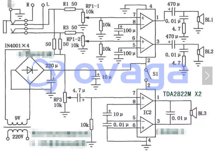
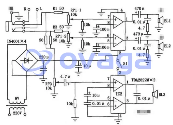
A 2.1-channel amplifier circuit composed of two TDA2822M integrated circuits
The circuit of the small bedside listening system is shown in the figure. This audio system uses two TDA2822M integrated circuit, has a small size, simple assembly, good sound effect, especially to strengthen the bass effect, very suitable for living in a group dormitory "audiophile" family production. IC1, IC2 are stereo amplifier integrated circuit TDA2822M, which IC1 IC1 is a dual-channel power amplifier circuit, the audio source signal through the resistor R1, R3 and duplex potentiometer RP1-1, RPl-2 sent to ICl for power amplification, the amplified audio signal to promote the speaker BL1, BL2 work.
IC2 constitutes a bass effect amplifier in the form of a BTL circuit, which is controlled by switch Sl when in use. Due to the large power consumption of the BTL circuit, IC2 should be installed with an appropriate heat sink. In addition, because the bass effect amplifier is not equipped with a low-pass filter, in the process of use, should try to use the tone control circuit of the source machine or the use of small bass speakers to enhance the bass effect.
TDA2822m Application Circuit Diagram (II)
Simple and easy to make the TDA2822M amplifier circuit diagram
The general collector amplifier circuit has more peripheral components and requires a larger heat sink. This article introduces the amplifier circuit is simple and easy to make your own. The circuit is shown in Figure 5-107. With a TDA2822M amplifier integrated circuit connected to the BTL mode, peripheral components only a resistor and two capacitors, without installing a heat sink, the sound effect is also satisfactory.
Integrated circuit TDA2822M for the 8-pin double inline package, if you can not buy TDA2822 instead, TDA2822 package and TDA2822M the same, they differ: TDA2822M from 3V to 15V can work, while the TDA2822 maximum operating voltage of only 8V. use TDA2822 must be lowered to 8V or less. The value of R1 is not required, generally choose 10k carbon film resistor. C1 can choose 0.1uF polyester capacitor, C2 is 100uF/160V electrolytic capacitor.
Figure 5-108 is the printed circuit board diagram. Because of the circuit is simple, the printed board can be used to spade carving method role of water abrasive sandpaper or kraft paper with a small amount of water polishing, wash and dry with water, coated with a layer of rosin alcohol solution, dry the components directly soldered in the copper foil surface can be. Solder and check that there is no error, then first not connected to the speaker, connected to the power supply, the voltage between the positive and negative outputs should be less than 0.1 V. Connect the speaker, touch the input by hand, the speaker should emit a large "buzz" sound. At this point, you can input the signal to try the sound. Circuit board without drilling.
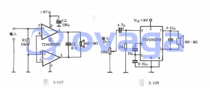
Use should pay attention to: because the amplifier is directly coupled, so the input signal can not be with DC components. If the input signal has DC components must be connected in series with a capacitor of about 10uF at the input to separate, otherwise there will be a large DC current flowing through the speaker, so that the heat burned. In practice, if the Figure 5-107 and then the appropriate modification is more satisfactory. The improved circuit shown in Figure 5-109.
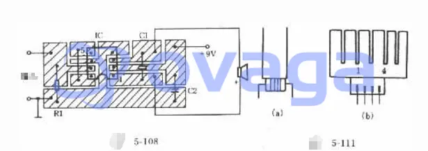
In use found that the volume is open to the maximum when the TDA2822M heat hot, so the TDA2822M made to the heat sink, as shown in Figure 5-110. Heat sink with a thickness of lmm, 38mm long, 25mm wide aluminum sheet made. And in the heat sink on the open 5 to 6 long 10mm, lmm wide slot, and then do the heat sink along the dotted line folded into a "mouth" shape.
Install the heat sink first in the TDA2822M put some silicone grease (silicone grease can be cut open 3AX31 or 3AX81 tube housing to take). According to Figure 5-111 (a) with a thin wire tied tightly can be. It should be noted that the number of pins of the TDA2822M is written on the side of the heatsink to avoid mistakes when soldering. After adding the heat sink, the volume is turned on to the maximum heat sink only a little warm, good heat dissipation. This method can also be used for other small integrated circuits for heat dissipation. We use two amplifier circuit made into a Walkman stereo power connector to promote two small speakers, the effect is very good.
In fact, not so complicated, directly connected to the corner of the tube, connected to the speaker, the audio source, plus 6 to 12V DC power can be. But change to a different source and speakers, I found that the 2822 is okay. Easy to do, the cost is also low, much stronger than the market to buy the kind of cheap active speakers.
TDA2822m Application Circuit Diagram (III)
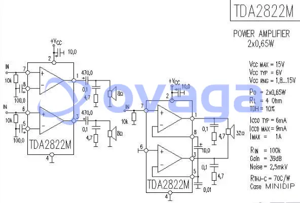
TDA2822M Power Amplifier Circuit Diagram
TDA2822m Application Circuit Diagram (iv)
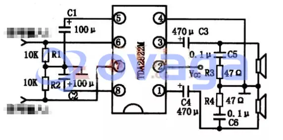
TDA2822M Typical Application Circuit Diagram
The typical application circuit of TDA2822 and TDA2822M integrated blocks are basically the same, as shown in the following figure.
TDA2822m Application Circuit Diagram (V)
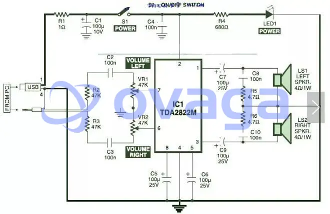
This is the circuit schematic of USB powered computer speaker, which is widely used in computer multimedia speakers. The circuit's single chipbased design, low-voltage electrical power supply, computer USB power supply compatibility, simple heat dissipation, low price, large flexibility and wide temperature tolerance.
At the heart of the circuit is the IC TDA2822M. In fact, this IC is in a monolithic 8 lead-free micro DIP (double in-line package). The TDA2822M features very low quiescent current, low crossover distortion, DC supply voltage down to 1.8 volts, minimum output power of about 450 mW/channel, and 5V DC supply input to 4 ohm speakers.
An ideal amplifier can essentially be used as a circuit which can deliver to an external load without generating large amounts of signal distortion and audio power without drawing extreme quiescent current.
The circuit is powered by a 5V DC power supply solicited from the computer's USB port. When the power switch S1" is turned on the stand, the 5V power supply is extended to the circuit and the power indicator red LED1 immediately lights up. Resistor R1 is actually a current surge limiter and capacitors C1 and C4 work as buffers.
TDA2822m Application Circuit Diagram (VI)
TDA2822M make a simple stereo amplifier + subwoofer
Extended Reading
 FAQ
FAQ
-
What are the typical applications of the TDA2822M audio amplifier circuit?
The TDA2822M audio amplifier circuit is suitable for a variety of low-power audio applications, such as: Portable audio devices, including MP3 players, smartphones, and tablets. Small radios, transceivers, and walkie-talkies. Intercom systems and doorbells. Audio amplification in toys and electronic games. Low-power speaker systems for computers and multimedia devices.
-
How can I connect and configure the TDA2822M in bridge-tied load (BTL) mode?
To configure the TDA2822M in bridge-tied load (BTL) mode, follow these steps: Connect the input signal to pin 1 (input 1) and pin 9 (input 2). Connect the two loudspeaker terminals to pins 3 and 5, which will serve as the BTL output. Connect the positive power supply (Vcc) to pin 6 and the ground (GND) to pin 4. To minimize noise and improve stability, place a decoupling capacitor (typically 100µF) between the Vcc and GND pins, as close to the IC as possible. In BTL mode, the TDA2822M provides increased output power and improved efficiency compared to the standard stereo configuration.
-
What is the TDA2822M audio amplifier circuit, and what are its main features?
The TDA2822M is an integrated circuit (IC) designed to function as a dual-channel audio power amplifier. It is commonly used in low-power applications like portable audio devices, radios, and intercom systems. Its main features include: Operating voltage range of 1.8V to 15V, allowing compatibility with a variety of power sources. Dual-channel (stereo) capability, enabling amplification of two separate audio signals. Low quiescent current consumption, making it suitable for battery-powered applications. Short-circuit and thermal protection, ensuring safe operation and preventing damage to the IC.
Popular Blogs
-
CR1220 Battery Equiv...
The CR1220 is a coin cell battery with a diamete...
-
CR2016 vs. CR2032: I...
CR2032 is used in electronic dictionaries, and C...
-
LR44 vs 357: Are LR4...
In button cell batteries, the LR44 and 357 have ...
-

Six TDA2822m Applica...
This article will introduce in detail six TDA282...
Hot Products

Popular Manufacturers