

What is Integrated Circuit Design?- How to Design?
Update Time: May 12, 2023 Readership: 4807
Contents
Brief Description
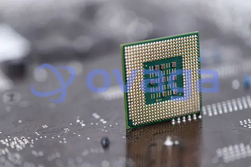
Integrated circuit design, IC design, also known as VLSI design, refers to the design process that targets integrated circuits and very large scale integrated circuits. IC design involves the modeling of electronic devices (e.g. transistors, resistors, capacitors, etc.) and interconnections between devices. All devices and interconnects need to be placed on a semiconductor substrate material, and these components are placed on a single silicon substrate through a semiconductor device manufacturing process (e.g., photolithography, etc.) to form the circuit.
Definition
The substrate material most commonly used in integrated circuit design is silicon. Designers use techniques to electrically isolate devices on the silicon substrate from each other to control the conduction between devices across the chip. PN junctions, metal oxide semiconductor field effect transistors, etc. constitute the basic structure of integrated circuit devices, and the complementary metal oxide semiconductors composed of the latter have become the most important components in digital integrated circuits due to their advantages of low static power consumption and high integration. Basic construction of logic gates. Designers need to consider the energy dissipation of transistors and interconnecting lines. This is different from building circuits from discrete electronic components in the past. This is because all the components of an integrated circuit are integrated on a single silicon chip. Electromigration of metal interconnects and electrostatic discharge are often detrimental to devices on microchips and are therefore issues of concern for integrated circuit design.
As the scale of integrated circuits continues to increase, its integration level has reached the deep submicron level (feature size below 130 nanometers), and the number of transistors integrated in a single chip has approached one billion. Due to its extreme complexity, integrated circuit design often requires computer-aided design methodology and technical means compared with simple circuit design. The research scope of integrated circuit design covers the optimization of digital logic in digital integrated circuits, the realization of netlists, the writing of register transfer level hardware description language codes, the verification, simulation and timing analysis of logic functions, the distribution of circuit connections in hardware, The placement of devices such as operational amplifiers and electronic filters in analog integrated circuits and the processing of mixed signals. Relevant research also includes electronic design automation (EDA) of hardware design, computer aided design (CAD) methodology, etc., which is a subset of electrical engineering and computer engineering.
For digital integrated circuits, designers are more at the high-level abstraction level, that is, register transfer level or even higher system level (some people also call it behavioral level), using hardware description language or advanced modeling language to describe The logic and timing functions of the circuit, and logic synthesis can automatically convert the hardware description language at the register transfer level into a netlist at the logic gate level. For simple circuits, designers can also use hardware description language to directly describe the connection between logic gates and flip-flops. After further functional verification, layout, and wiring of the netlist, a GDSII file for industrial manufacturing can be generated, and the factory can manufacture circuits on the wafer according to the file. The design of analog integrated circuits involves a more complex signal environment, which has higher requirements for the experience of engineers, and the degree of automation of its design is far less than that of digital integrated circuits.
Stepping through the functional design, the design rules that dictate which designs match manufacturing requirements and which don't match are complex in themselves. Integrated circuit design flows need to match hundreds of such rules. Under certain design constraints, the layout and routing of the physical layout of the integrated circuit are critical to achieving the desired speed, signal integrity, and reduced chip area. The unpredictability of semiconductor device manufacturing further increases the difficulty of integrated circuit design. In the field of integrated circuit design, due to the pressure of market competition, related computer-aided design tools such as electronic design automation have been widely used. Engineers can perform register transfer level design, functional verification, static timing analysis, and physical design with the assistance of computer software. Wait for the process.

Abstract Level
Integrated circuit design is usually based on "modules" as the unit of design. For example, for a multi-bit full adder, the next level module is the adder of a bit, which in turn is composed of the next level of with and without gate modules, which can eventually be decomposed into CMOS devices at a lower abstraction level.
From the abstraction level, digital integrated circuit design can be top-down, that is, first defined the highest logic level of the system functional modules, according to the needs of the top-level modules to define sub-modules, and then continue to decompose layer by layer; design can also be bottom-up, that is, first designed the most specific modules, and then as building blocks to use these bottom modules to implement the upper modules, and finally reach the highest level. In many designs, top-down and bottom-up design methodologies are mixed, with system-level designers planning the overall architecture and performing the sub-module division, while bottom-level circuit designers design and optimize the individual modules layer by layer upward. Finally, designers from both directions meet at some intermediate level of abstraction to complete the overall design.
Hardware Implementation
For different design requirements, engineers can choose to use a semi-custom design path, such as implementing hardware circuits using programmable logic devices (field-programmable logic gate arrays, etc.) or specialized integrated circuits based on standard cell libraries, or they can use a full-custom design, controlling all the details from transistor layout to system architecture.
Full Custom Design
This design approach requires the designer to use a layout editor to complete the layout design, parameter extraction, cell characterization, and then use these cells of their own design to complete the circuit construction. Typically, full custom designs are designed to maximize and optimize circuit performance. If a desired cell is missing from the standard cell library, a full custom design approach is also required to complete the desired cell design. However, this design approach usually takes a longer time.
Semi-custom design
The opposite of full custom design is semi-custom design. In short, semi-custom IC design is based on pre-designed certain logic cells. For example, designers can design specialized ICs based on a library of standard components (which can usually be purchased from a third party), from which they can select the required logic units (e.g., various basic logic gates, flip-flops, etc.) to build the desired circuit. They can also be designed using programmable logic devices, where almost all the physical structure is already fixed in the chip, leaving only certain connections to be programmed by the user to determine how they are connected. The performance parameters associated with these pre-designed logic units are also usually provided by their suppliers to facilitate timing and power analysis by designers. The advantages of implementing a design on a semi-custom field-programmable logic gate array (FPGA) are short development cycles and low cost.
Programmable Logic Devices
Programmable logic devices are usually provided by semiconductor manufacturers with commodity chips that can be connected to a computer via JTAG, for example, so designers can use electronic design automation tools to complete the design and will then use the design code to program the logic chip. Programmable logic array chips are defined in advance of the factory to form an array of logic gates, and the connection lines between logic gates can be programmed to control connections and disconnections. With the development of technology, programming of the connection lines can be achieved by EPROM (using higher voltage electrical programming and UV irradiation to erase), EEPROM (using electrical signals to program and erase multiple times), SRAM, flash memory, etc. Field-programmable logic gate arrays are a special type of programmable logic devices, which are physically based on configurable logic cells and consist of structures such as lookup tables, programmable multiplexers, and registers. Lookup tables can be used to implement logic functions, such as lookup tables for three inputs to implement all three-variable logic functions.
Specialized ICs
The advantage of an application-specific integrated circuit (ASIC) designed for a specific application is that area, power consumption, and timing can be optimized to the maximum extent. ASICs can only be manufactured after the entire IC design has been completed and require the involvement of a specialized semiconductor fab. A dedicated IC can be based on a standard cell library or a fully customized design. In the latter route, the designer has more control over the placement and connectivity of components on the wafer, unlike the programmable logic device route, where only some of the hardware resources can be selected for use, resulting in some resources being wasted. The area, power consumption, and timing characteristics of dedicated ICs can often be better optimized. However, the design of a dedicated IC can be more complex and requires a dedicated process manufacturing department (or outsourcing to a foundry) to fabricate the GDSII file into a circuit. Once a dedicated IC chip is manufactured, the logic function of the circuit cannot be reconfigured as it can be with programmable logic devices. For individual products, the economic and time costs of implementing an IC on a dedicated IC are higher than those of a programmable logic device, so programmable logic devices, especially field-programmable logic gate arrays, are commonly used in the early design and debug process; if the designed IC is to be put into production in large quantities at a later stage, then mass production of dedicated ICs will be more economical.

How to Design
Integrated circuit design can be broadly divided into two categories: digital integrated circuit design and analog integrated circuit design. However, actual integrated circuits may also be mixed-signal integrated circuits, so many circuits are designed using both processes.
Analog Integrated Circuits
Another large branch of IC design is analog IC design, and this branch usually focuses on power ICs, RF ICs, etc. Since real-world signals are analog, integrated circuits for analog-to-digital and digital-to-analog interconversion also have a wide range of applications in electronic products. Analog integrated circuits include operational amplifiers, linear rectifiers, phase-locked loops, oscillation circuits, active filters, etc. Compared with digital IC design, analog IC design is more related to the physical properties of semiconductor devices, such as their gain, circuit matching, power dissipation and impedance, etc. Analog signal amplification and filtering requires a certain degree of fidelity of the circuit, so analog integrated circuits use more large-area devices than digital integrated circuits, and the integration level is relatively low.
Before the advent of microprocessors and computer-aided design methods, analog integrated circuits were completely designed manually. Because of the limited human ability to deal with complex problems, the analog integrated circuits at that time were usually more basic circuits, and operational amplifier integrated circuits were a typical example. In those days, such an integrated circuit might involve a dozen transistors and the interconnecting wires between them. In order to bring the design of an analog integrated circuit up to the level of industrial production, engineers need to take several iterations to test and troubleshoot. After the 1970s, the price of computers gradually decreased, and more and more engineers could use this modern tool to assist in design, for example, by using a programmed computer for simulation, they could obtain a higher level of accuracy than the previous manual calculation and design. spice was the first software for analog integrated circuit simulation software (in fact, the design of the standard cell itself in digital integrated circuits, also need to use SPICE for parameter testing), which literally means Simulation Program with Integrated Circuit Emphasi, based on the computer-aided design of circuit simulation tools can adapt to more complex modern integrated circuits, especially dedicated integrated circuits.
The use of computers for simulation also allows some errors in project design to be detected before the hardware is manufactured, thus reducing the significant costs caused by repeated testing and troubleshooting. In addition, computers are often able to perform tasks that are extremely complex, tedious, and beyond human capabilities, making things such as the Monte Carlo method possible. Deviations from the ideal situation that would be encountered in actual hardware circuits, such as temperature deviations and deviations in the concentration of semiconductor doping in the device, can also be simulated and handled by computer simulation tools. In short, computerized circuit design and simulation can lead to better circuit design performance and greater assurance of manufacturability. Nevertheless, the design of analog integrated circuits requires more experience and the ability to weigh contradictions than digital integrated circuits.
Digital Circuits
Roughly speaking, digital integrated circuits can be divided into the following basic steps: system definition, register transfer level design, and physical design. In turn, the design is divided into system behavior level, register transfer level, and logic gate level according to the abstraction level of logic. Designers need to write functional codes, set up synthesis tools, verify logic timing performance, plan physical design strategies, etc. in a rational manner. At specific points in the design process, multiple checks and debugging of logic functions, timing constraints, and design rules are required to ensure that the final design meets the initial design convergence goals.
System Definition
System definition is the initial planning of the IC design, where the designer needs to consider the macro functionality of the system. Designers may use a number of high abstraction level modeling languages and tools to complete the hardware description, such as C, C++, SystemC, SystemVerilog, and other transaction level modeling languages, as well as tools such as Simulink and MATLAB to model the signals. Although the mainstream is centered on register transfer level design, there are already some high-level synthesis (or behavioral level synthesis) and high-level verification tools that are in the development stage of transforming directly from system level description to lower abstraction level description (e.g., logic gate level structure description). The system definition phase, the designer also plans the expected process, power consumption, clock frequency frequency, operating temperature and other performance indicators of the chip.
Register Transfer Level Design
Integrated circuit design is often performed at the register transfer level, using hardware description languages to describe the storage of signals in digital integrated circuits and the transfer of signals between logic units such as registers, memories, combinational logic devices, and buses. When designing register transfer level code, the designer converts the system definition into a register transfer level description. The two most common hardware description languages used by designers at this level of abstraction are Verilog, and VHDL, which were standardized by the Institute of Electrical and Electronics Engineers (IEEE) in 1995 and 1987, respectively. Thanks to hardware description languages, designers can focus more on functional implementation, which is more efficient than the previous methodology of directly designing logic gate-level connections (it is still possible to directly design gate-level netlists using hardware description languages, but fewer people work that way).
Design Verification
After the designer completes the register transfer level design, he or she uses testbenches, assertions, etc. to perform functional verification to verify that the project design matches the previous functional definition and, if there are errors, to detect any gaps in the previous design files. The time and effort required for verification throughout the design process of modern exascale integrated circuits is increasing, even all over the register transfer level design itself, and people set some new tools and languages developed specifically for verification.
For example, to implement a simple adder or a more complex arithmetic logic unit, or to implement a finite state machine using flip-flops, designers may write hardware description language code of different scales. Functional verification is a complex task in which the verifier creates a virtual external environment for the design under test, provides input signals to the design under test (this artificially added signal is often represented by the term "excitation"), and then observes whether the output ports of the design under test function according to the design specification.
When the circuit under design is not simply a few inputs and outputs, the definition of the excitation signal becomes more complex because the verification needs to take into account as many input scenarios as possible. Sometimes engineers use certain scripting languages (e.g. Perl, Tcl) to write verification programs to achieve greater test coverage with the high-speed processing of computer programs. Modern hardware verification languages can provide some features specifically for verification, such as randomized variables with constraints, overlays, etc. As a unified language for hardware design and verification, SystemVerilog was developed based on Verilog, so it has both design features and testbench features, and introduces the idea of object-oriented programming, so the testbench is written closer to software testing. Standardized verification platform development frameworks such as the Common Verification Methodology are also supported by mainstream electronic design automation software vendors. For advanced synthesis, electronic design automation tools on advanced verification are also under research.
Logic Synthesis
The hardware description language code designed by engineers is typically register-transfer level and requires logic synthesis tools to convert the register-transfer level code to process-specific logic gate-level netlists and complete logic simplification before proceeding with the physical design.
Similar to manual logic optimization that requires the use of Carnot diagrams, etc., electronic design automation tools to complete logic synthesis also require specific algorithms (e.g., Quinn-McCluskey algorithm, etc.) to simplify the logic functions defined by the designer. The files entered into the automated synthesis tool include three main categories: register transfer level hardware description language code, process libraries (which can be provided by third-party foundry services), and design constraint files, which may have different formats in different electronic design automation toolkit systems. The logic synthesis tool produces an optimized gate level netlist, but this netlist is still based on the hardware description language and the alignment of this netlist in the semiconductor chip will be done in the physical design.
The selection of process libraries corresponding to different devices (e.g., dedicated integrated circuits or field-programmable gate arrays, etc.) for logic synthesis, or the setting of different constraint strategies during synthesis, will produce different synthesis results. Factors such as the logic plan score of register transfer level code for the design project and the language structure style will affect the efficiency of the synthesized netlist. Most mature synthesis tools are mostly based on register transfer level descriptions, while advanced synthesis tools based on system level descriptions are still in the development stage.
Formal Equivalence Check
To compare the equivalence of gate-level netlist and register-transfer level, formal equivalence checking (formal verification) can be accomplished by generating, for example, disjunctive satisfiability, binary decision diagrams, and so on. In fact, the equivalence check can also check the logical equivalence between two register transfer level designs, or between two gate-level netlists.
Timing Analysis
The clock frequency of modern integrated circuits has reached the megahertz level, and the timing relationships within and between a large number of modules are extremely complex. Therefore, in addition to verifying the logic function of the circuit, timing analysis is required, i.e., the delay of the signal in the transmission path is checked to determine whether it matches the timing convergence requirements. The standard delay format information for logic gates required for timing analysis can be provided by a library of standard cells (or timing information extracted from cells of the user's own design). As the circuit feature size decreases, interconnect delays become a more significant percentage of the actual total delay, so taking interconnect delays into account after the physical design is complete allows for accurate timing analysis.

Physical Design
After the logic synthesis is completed, by introducing the process information provided by the device manufacturing company, the previously completed design will enter the layout planning, layout, and wiring phase. Engineers need to set the parameters of the physical design tool reasonably based on the constraint information of latency, power consumption, and area, and continuously debug to get the best configuration to decide the physical location of the component on the wafer. In case of full custom design, engineers also need to carefully draw the IC layout of the cell and adjust the transistor size so as to reduce power consumption and latency.
As the feature size of modern integrated circuits continues to drop, and exascale integrated circuits have entered the deep submicron stage, the impact of interconnect line delay on circuit performance has reached or even exceeded the impact of logic gate delay. At this point, factors to consider include the capacitive effect of the line network and the inductive effect of the line network, and the voltage drop caused by the high current on the line network resistor on the chip's internal power lines can also affect the stability of the integrated circuit. In order to solve these problems, while mitigating the negative impact of clock offset, clock tree parasitic parameters, a reasonable layout wiring and logic design, functional verification and other processes are equally important. With the development of mobile devices, low-power design is becoming more and more prominent in IC design. In the physical design phase, the design can be translated into a geometric representation, which is regulated by several standardized file formats (e.g., GDSII) in industry.
It is worth noting that the functions implemented in the circuit are defined in the previous register transfer level design. In the physical design phase, the engineer must not only not allow the previously designed logic and timing functions to be corrupted in that phase of the design, but also further optimize the chip's performance in terms of delay time, power consumption, area, etc. when operating correctly. After the physical design has produced the initial layout file, the engineer needs to verify the IC again in terms of functionality, timing, design rules, signal integrity, etc. to ensure that the physical design produces the correct hardware layout file.
Extended Reading
 FAQ
FAQ
-
What is the role of EDA tools in IC design?
Electronic Design Automation (EDA) tools play a vital role in IC design. These software tools help designers automate and optimize the design process. They assist with tasks such as schematic capture, simulation, synthesis, layout, and verification, improving design productivity and enabling faster time-to-market.
-
What are the major challenges in IC design?
IC design faces various challenges, including increasing circuit complexity, power consumption, and shrinking transistor sizes. Other challenges include maintaining signal integrity, ensuring manufacturability, and dealing with the growing complexity of design rules and process technologies.
-
What is RTL design in IC design?
RTL (Register Transfer Level) design is a step in IC design where the behavior and functionality of the circuit are described at the register transfer level. It involves defining the flow of data between registers and the operations performed on that data, without specifying the physical implementation.
Popular Blogs
-
What is Integrated C...
IC design, short for integrated circuit design, ...
-

Types and Applicatio...
As the world continues to search for sustainable...
-

What is an Analog In...
An analog integrated circuit mainly refers to an...
-

What Can ChatGPT Bri...
ChatGPT's popularity continues, and although it ...
Hot Products
-
-
-
Infineon Technologies Corporation
INFINEON - IFX9201SGAUMA1 - MOTOR CONTROLLER, HALF...
-
Infineon Technologies Corporation
solar inverters as well as SMPS and uninterruptibl...
-
Microchip Technology, Inc
32-bit Microcontrollers - MCU PIC32MK, 1MB Flash, ...
-
-
-
-
-
-
-
-
-
-
-
-
-
-
Infineon Technologies Corporation
EV charging: Off-board charging, where users can ...
-
-
-
-
-
-
-
-
-
-
-
-
-
-
-
-
-
-
-
-
-
-
-
-
-
-
-
-

-
-
-
Popular Manufacturers