
Microchip dsPIC33CK64MP105-I/PT MIC4104YM-Based High-Performance Electric Scooter Motor Driver Solution
Microchip's high-performance electric scooter motor driver reference design helps you easily meet the challenges of designing small mobility aids for small, low-cost, low-noise applications with regenerative braking.
The following video introduces the reference design, which offers the perfect balance of performance, cost and efficiency for Microchip's electric scooter motor driver reference design. The high-performance BLDC/PMSM motor driver board demonstrates the functionality provided by the dsPIC33CK high-performance digital signal controller (DSC) with the MIC4104 MOSFET gate driver for motor control applications. The entire system solution has been developed to meet the stringent requirements of modern motor control applications: high efficiency, compact size, low cost and high performance.
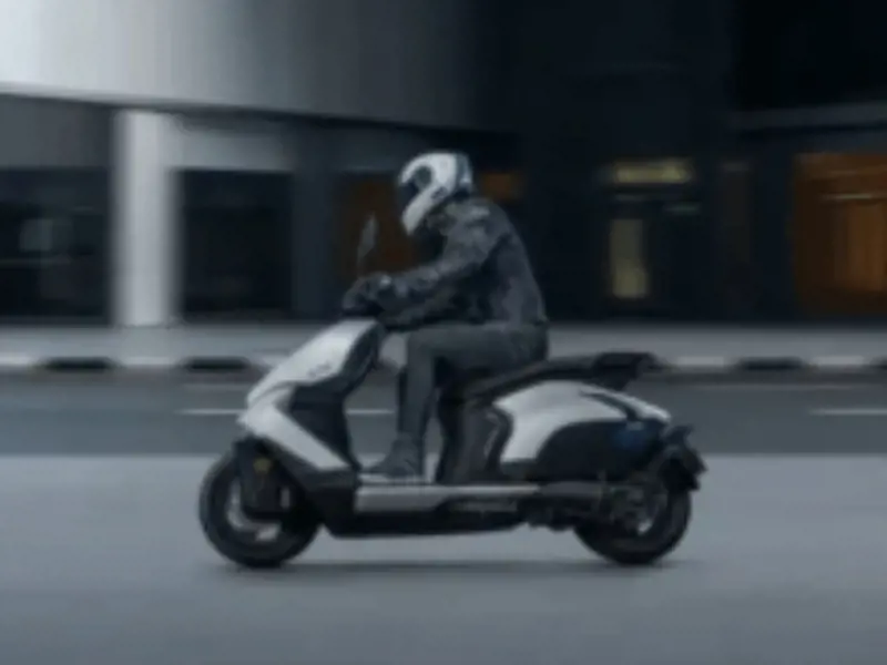
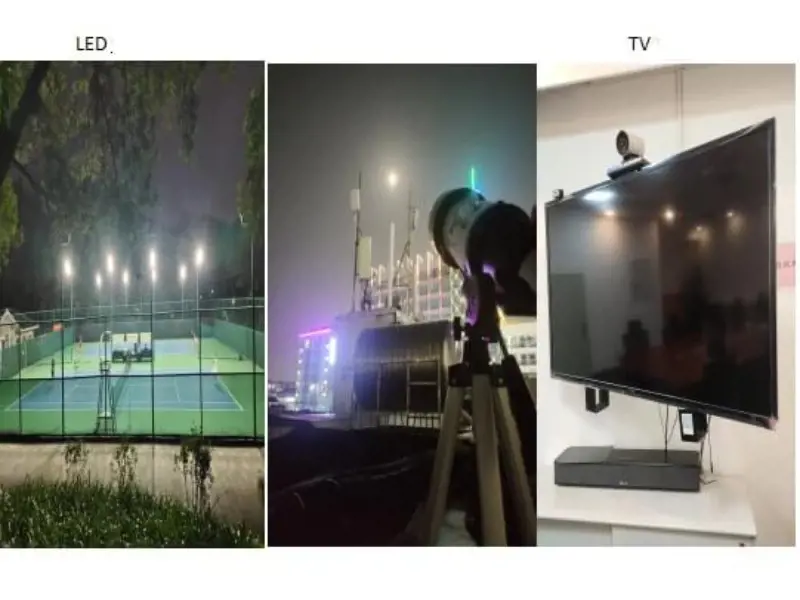
►Scenario Application Diagram

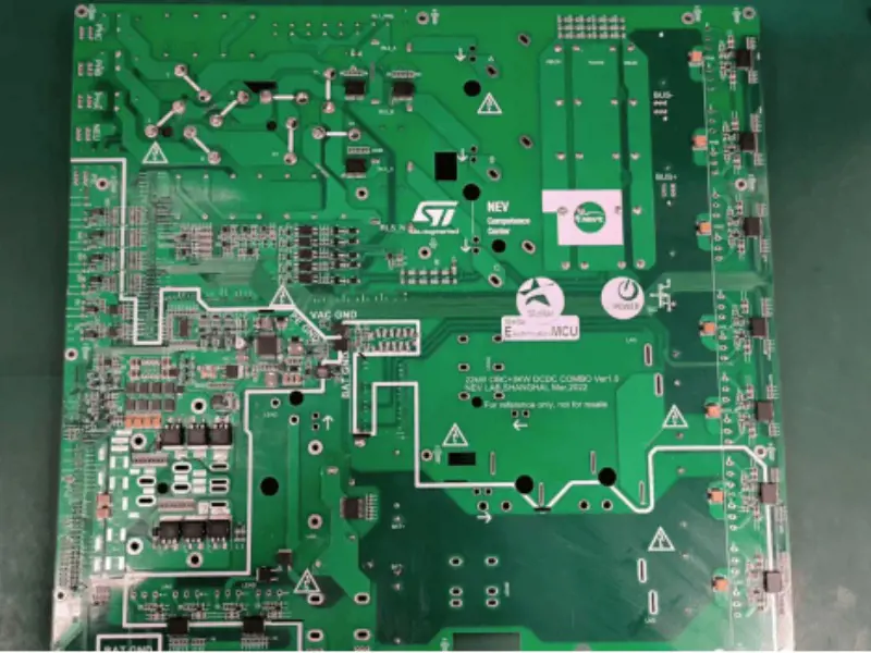
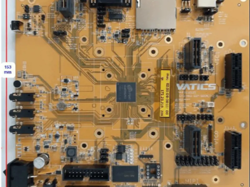
►Display board photo


►Solution cube diagram

►Phase current waveform with sensor mode

►Core technical advantages
1. Small size 60mmx50mm.
2. dsPIC33CK digital signal controller realizes efficient magnetic field directional control FOC algorithm with built-in advanced analog peripherals such as high speed op-amp and comparator.
3. Support Hall sensor and sensorless motor control applications.
4. sinusoidal phase current drive, very low noise operation, low current ripple, improve electrolytic capacitor life and reduce EMI.
5. the use of three lower bridge arm current detection resistors to measure the motor phase current.
6. Regenerative braking can significantly reduce the wear and tear of the mechanical braking system and improve battery life.
7. The bill of materials is optimized for space and cost.
►Specifications
1、Input voltage range 18V~42V.
2、Maximum phase current 15A(continuous), 27A(short time).
3、Maximum output power 250W(continuous), 800W(peak).
4、PWM frequency range 8KHz~50KHz.
5、Maximum PWM duty cycle 99%.
6、Phase overcurrent, input undervoltage/over-voltage, power inverter overheat protection.
7、Sense mode: low-speed use Hall six-step phase change, medium-speed linear interpolation, high-speed use angle observer.